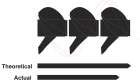
Propeller Terminology

The Michigan Wheel guide to understanding propellers. Here you will find everything from propeller parts to terminology that will help you understand how boat propellers work.

Filters

Track

The absolute difference of the actual individual blade height distributions to the other blade height distributions. Always a positive value and represents the spread between the individual blade height distributions.

Geometric Pitch Angle

The angle between the pitch reference line and a line perpendicular to the propeller axis of rotation.

Pitch Reference Line

Reference line used to establish the geometric pitch angle for the section. This line may pass through the leading and trailing edges of the section and may be equivalent to the chord line.

Cylindrical Section

A cross section of a blade cut by a circular cylinder whose centerline is the propeller axis of rotation.

Ventilation

A situation where surface air or exhaust gases are drawn into the propeller blades. When this situation occurs, boat speed is lost and engine RPM climbs rapidly. This can result from excessively tight cornering, a motor that is mounted very high on the transom, or by over-trimming the engine.

Slip

Slip is the difference between actual and theoretical travel of the propeller blades through water. A properly match propeller will actually move forward about 80 to 90 perfect of the theoretical pitch.

Skew

The transverse sweeping of a blade such that viewing the blades from fore or aft shows an asymmetrical shape. Aft skew is positive skew, where blades sweep in the direction opposite of rotation. Forward skew is negative skew, where blades sweep in the same direction as rotation.

Thru-Hub Exhaust

Thru-hub exhaust propellers consist of a round barrel to which the blades are attached. The exhaust passes through the barrel and out the back, without making contact with the propeller blades. This provides a good, clean water flow to the blades, usually resulting in good acceleration and hole shot.

Variable Pitch Propeller

The propeller blades have sections designed with varying values of local face pitch on the pitch side or blade face.

Constant Pitch Propeller

The propeller blades have the same value of pitch from root to tip and from leading edge to trailing edge.

Fixed Pitch Propeller

The propeller blades are permanently mounted and do not allow a change in the propeller pitch.

Controllable Pitch Propeller

The propeller blades mount separately on the hub, each on an axis of rotation, allowing a change of pitch in the blades and thus the propeller.

Trailing Edge

The edge of the propeller adjacent to the aft end of the hub. When viewing the propeller from astern, this edge is closest. The trailing edge retreats from the flow when providing forward thrust.

Rotation

When viewed from the stern (facing forward): Right-hand propellers rotate clockwise to provide forward thrust. Left-hand propellers rotate counter-clockwise to provide forward thrust.

Rake

Rake is the degree that the blades slant forward or backwards in relation to the hub. Rake can affect the flow of water through the propeller, and as implications with respect to boat performance. Aft Rake helps to trim the bow of the boat upward, which often results in less wetted surface area and therefore higher top end speed. Forward, or negative rake, helps hold the bow of the boat down. This is more common in workboat type applications.

Radius

The distance from the axis of rotation to the blade tip. The radius multiplied by two is equal to the diameter.

Pitch

Pitch is defined as the theoretical forward movement of a propeller during one revolution — assuming there is no “slippage” between the propeller blade and the water. Pitch is the second number listed in the propeller description.

Over/Thru-Hub Exhaust

Over/Thru-hub exhaust propellers are a combination of thru-hub and over-hub exhaust propellers. This allows some exhaust to escape at lower RPMs, providing a controlled amount of exhaust flooding. These types of propellers will allow the propeller to be slightly easier to turn during initial acceleration, allowing for a better hole shot on some engine/boat combinations.

Over-Hub Exhaust

Over-hub exhaust propellers have the blades attached directly to the smaller tube that fits over the propeller shaft, eliminating the larger exhaust tube. These types of propellers are often used for attaining maximum top speeds. (On some boats, the hole shot can suffer due to extreme exhuast flooding that occurs around the propeller blades during acceleration.)

Non Thru-Hub Exhaust

Non thru-hub exhaust propellers are used for inboards using shaft driven propellers, sterndrives using through hull exhaust, and on some outboards that don’t route the exhaust through the lower topedo.

Leading Edge

The edge of the propeller blade adjacent to the forward end of the hub. When viewing the propeller from astern, this edge is furthest away. The leading edge leads into the flow when providing forward thrust.

Hub

Solid cylinder located at the center of the propeller. Bored to accommodate the shaft. Hub shapes include cylindrical, conical, & barreled.

Diameter

Diameter is two times the distance from the center of the hub to the tip of the blade. It can also be looked at as the distance across the circle that the propeller would make when rotating. This is the first number listed when describing a propeller.

Cup

Small radius of curvature located on the trailing edge of the blade. This curved lip on the propeller blade increases efficiency in high speed/high RPM applications where the propeller is cavitating.

Cavitation

Cavitation, (which is often confused with ventilation), is a phenoma of water vaporizing or “boiling” due to the extreme reduction of pressure on the back of the propeller blade. Many propellers partially cavitate during normal operation, but excessive cavitation can result in physical damage to the propeller’s blade surface due to the collapse of the microscopic bubbles on the blade. There may be numerous causes of cavitation such as incorrect matching of propeller style to application, incorrect pitch, physical damage to the blade edges, etc

Blade Tip

Maximum reach of the blade from the center of the hub. Separates the leading and trailing edges.

Blade

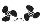
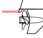
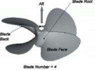
Blade Back Suction side. Forward side of the blade (surface facing the bow). Blade Face Pressure Side, Pitch Side. Aft side of the blade (surface facing the stern). Blade Number Equal to the number of blades on the propeller. Blade Root Fillet area. The region of transition from the blade surfaces and edges to the hub periphery. The area where the blade attaches to the hub.